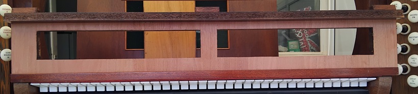
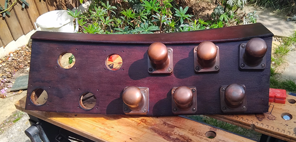
Here it is, varnished and felted, with the felt still to trim. I’m pleased with how well the colour matches the existing veneer; not bad for what was essentially guesswork.
And here it is in situ. It will need to be screwed to the keyframes, but I’m not feeling brave enough for that yet.
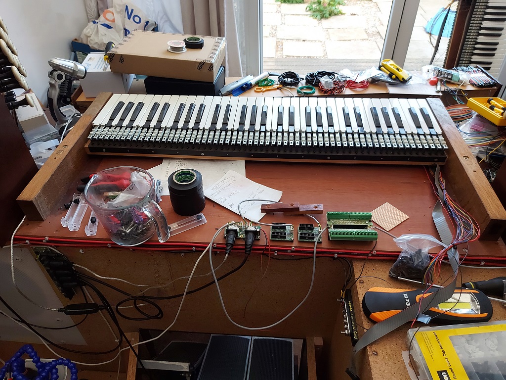
Still awaiting the mesh from surfacescan.co.uk, which should be here in the next week or so. In the meantime I am working on a prototype of the interstitial converter board, which takes the matrix output from the rocker tabs and turns it into 32 discrete signals (16 for on, 16 for off) which the BBS1K can understand.
I have finished staining and varnishing, and it looks quite good. Photo in the next installment.
There are several sub-projects on the go:
Finishing the panel (drilling and felting). This depends on there being a warm, sunny day when I’m not at work. Possibly next weekend.
Replacement rocker tabs. I have sent a sample off to surfacescan.co.uk, and I am awaiting the finished mesh (probably a couple of weeks). I think they will be able to produce my new tabs, too.
Interstitial circuit. I need to convert the tab board matrix output into discrete ouputs, using a SOC and some ‘555 chips. This is the project currently burning holes in my brain.
The rocker-tab bar is now with the joiner. He doesn’t think it will be a big job, but I also need to send him some veneer to apply. Naturally enough, I don’t have quite enough veneer remaining, so I’ve had to order another batch. Grr.
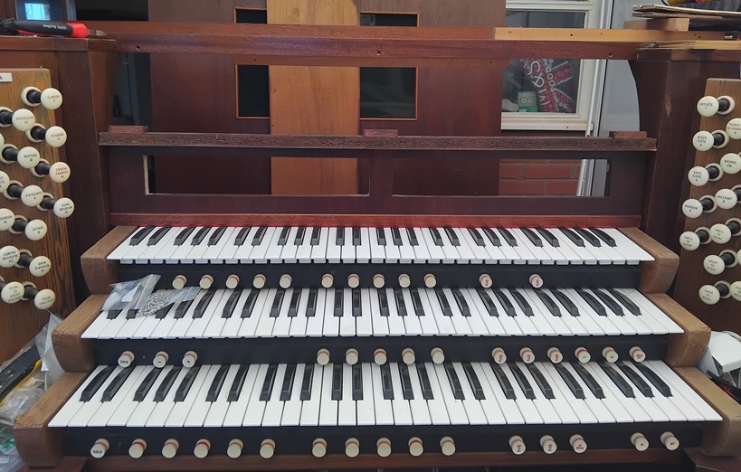
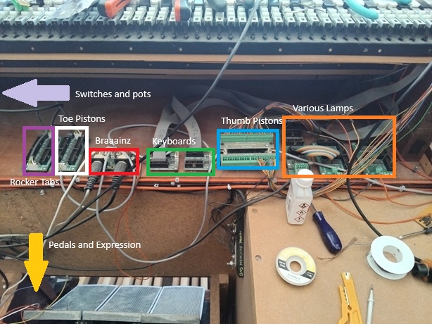
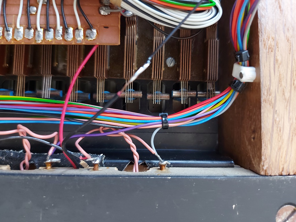
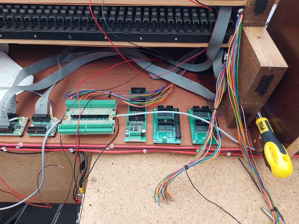
Meanwhile, here is what the back of the organ currently looks like. It’s mostly so that I have a reminder of what is going where, but others may find it instructive.
Red: The brains. This is the board which actually sends (and sometimes receives) MIDI messages. All of the components which will send events to Hauptwerk go through here.
Green: The keyboards. There are three physical keyboards, and they are plugged in here.
Yellow (not shown): The pedalboard and expression shoes. This module is actually on the pedalboard itself, and connected by a long wire.
Blue: Thumb pistons. All of the pistons under the keyboards go through this module.
Orange: Lamps. This is a MIDI-IN module, and turns various lights on and off when it receives the appropriate MIDI signal: the rocker tabs and the Solo indicator.
White: Toe pistons. Like the thumb pistons, but for the feet.
Dark purple: Rocker tabs. These are on-off signals from the rocker tabs.
Light purple (not shown): Various switches and pots on the console – they were already there, so they can be wired up if I can come up with a good reason for them.
Also not shown in this photo are the drawstop subsystems, which are in/out components. A MIDI-OUT message is generated when pulling out (or pushing in, for that matter) an individual stop, but MIDI-IN messages are also received and activate the individual drawstop solenoids. This means that depressing a thumb- or toe-piston can change the registration mechanically.
The next job, while I’m waiting for the rocker-tab bar to be returned, is to wire up the toe pistons. Once that’s done, the organ will theoretically be playable through my laptop, at least in a small way.
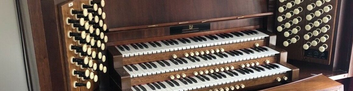
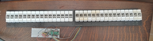
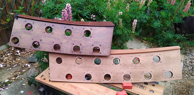
I have two banks of rocker tabs from another Wyvern instrument, making 32 tabs in all. This will give me more options for coupling than I can shake even a very large stick at:
These will sit across the top of the swell manual, directly underneath the music stand. I think this is an American style, and I rather like it.
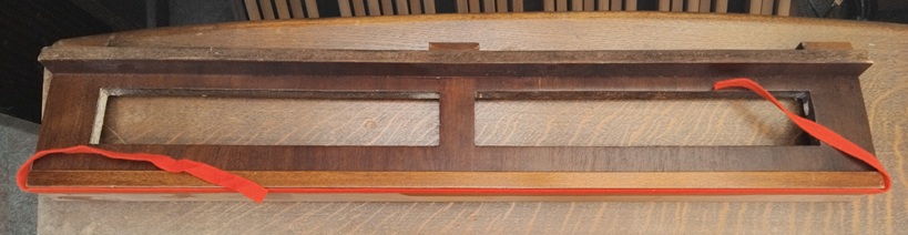
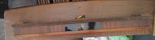
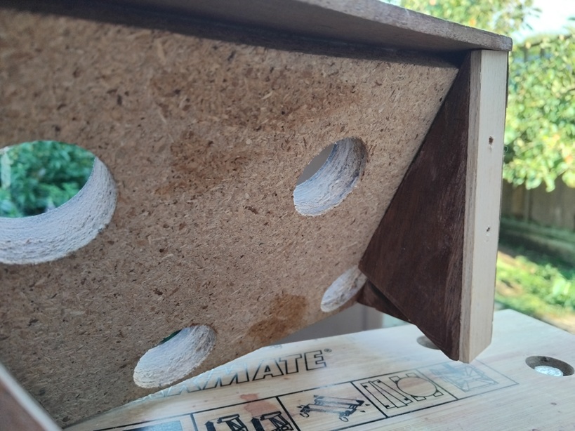
Here is the moulding which sat atop the old keyboards. It’s about 35mm too narrow, unfortunately:
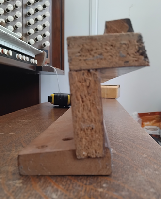
And here is the profile. It is slightly angled, so not a straightforward replacement:
So my next job will be to find a local bespoke woodworker and see if they can make me a replacement that the rocker tabs will fit into. The tab blocks are matrixed, so I also have to design a piece of electronic magic to convert this into discrete outputs. I’m idly speculating about doing it with a Raspberry Pi Zero running a bit of Python, but I might not have enough i/o, The second option is to design a circuit that decodes the matrix using a series of shift registers. The second is probably the cleaner approach, but I like writing Python.
Last post on 3rd October 2022. That’s outrageous. Sorry, life got in the way.
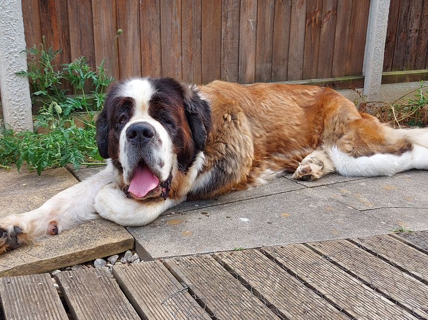
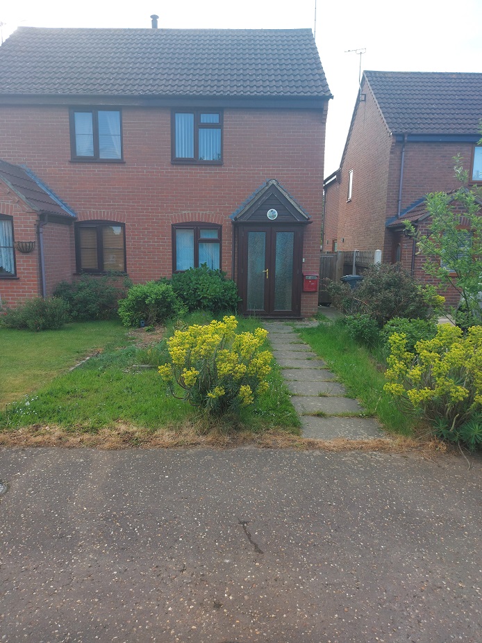
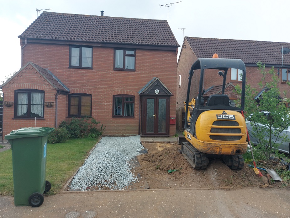
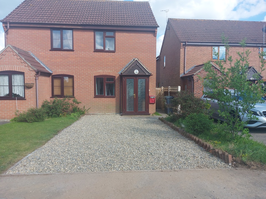
Let’s see? What has happened (this nice bits, anyway)? I got a new car. I had a small extension built on the front of the house. I bought a new rose for the garden. I did a few bits of work on the organ. Also, Xera came to stay.
She weighs 66kg, but it’s not nice to comment on a lady’s weight. The poor girl had a very bad puppyhood and is terrified of people. I visited the rescue centre every day for six months before she trusted me enough to bring her home. She trusts me completely now, but she wants to eat anyone else who comes within about 20 yards. This is unfortunate, because she really is a beautiful girl, and Dyson worships her. She likes to sit on my plants.
Drawstops
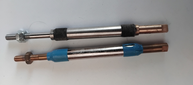
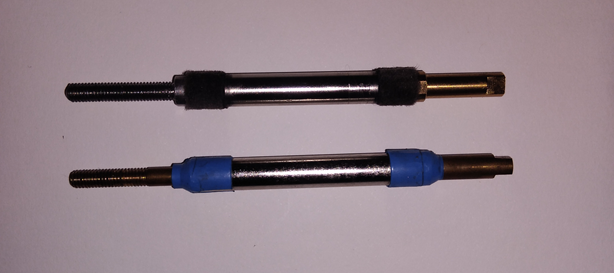
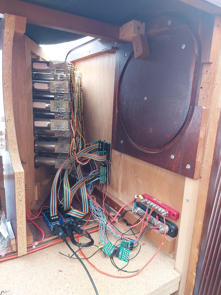
Multiple things have happened with the organ, although not nearly as much as I had hoped. That whole “life” thing again, you know. I have new armatures for the drawstops – purchased from Kimber-Allen, the manufacturers of the original drawstops but – alas! – they are marginally longer than their predecessors. Fortunately a local engineering firm was able to extend the thread down the armature and chop off about a quarter of an inch from the end to make them the replacements the same size as the originals. I’m delighted to say that this has worked perfectly, and eventually I will get around to replacing all the armatures. I’ve done two – only sixty-seven left.
BeforeAfter
Toe pistons
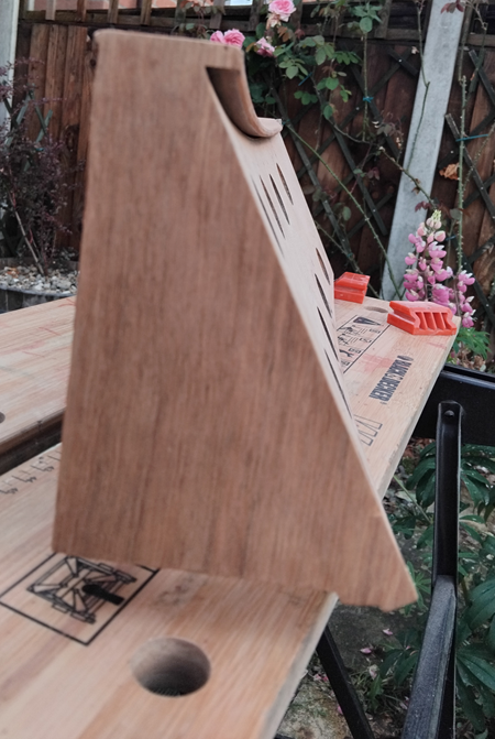
I have modified the toe piston blocks to make them fit around the expanded expression shoe opening., even managing to add a couple of additional pistons, which was a surprise. I have re-fitted the blocks to the organ, but I didn’t think to take a photo of the finished work. As a consolation prize, here are some photos of the work in progress.
New veneer!Endpiece replaced and padded outBottom piece stripped ready for stain and varnishFinished piece having pistons re-fitted
Expression shoes – an exercise in pain
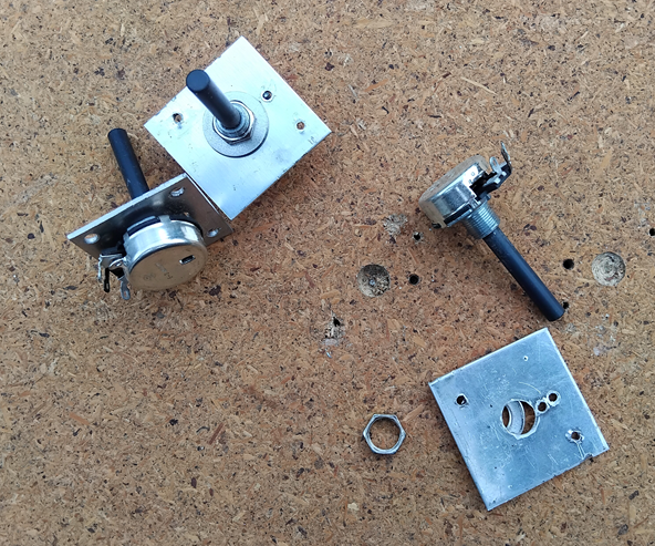
And then we come to the expression shoes. These things took me a YEAR to get right, which comprised periods of manic busyness followed by extended bouts of sulking. In essence, the old pots were failing (not surprising given that they were over 40 years old), but it took me a long time to prove this and thereby establish that it wasn’t the MIDI hardware being odd. Then it took months to find exactly the right replacements. Then I had to disassemble the whole subassembly (Thirty. Four. Screws.) and modify the individual shoe housings to take the new pots, which were just fractionally larger. The end result is that they now work beautifully, but getting there was one of the more painful experiences of the journey to date.
New pots being assembled
So there we have it. And now it is 2026. At some point in the next few weeks I am going to give the console a good tidy-up and dust-down, and then take stock of where we go next. Now I have fully reassembled the pedalboard the organ should be playable again, even if I have to use the laptop to control the sound output. The next phase of the project is to install the rocker tabs – which will also require me to design some electronic shenanigans to map the matrix to unique outputs.
I have been preoccupied with house maintenance for the last few weeks (and playing with my shiny! new! car!). There will be another update on the organ soon, once the toe pistons are returned and plugged in again. And I still have to tell you all about the rocker tabs.
I keep waiting for something to go horribly wrong.
Following on from yesterday’s success, I was able to confirm today that the reed switches are all behaving properly. This means that both stop jambs are now functional. I still have to program the BBS-1K modules that they plug into, but that’s a trivial detail (he said, sealing his fate). Today’s activity centred around unscrewing the manuals. I didn’t think I’d have to do that again, but there you go.
When I first wired up the manuals, I connected the 0V wire of the LED to the common ground of the thumb pistons. Now I come to actually wire them up, I realise that this is incorrect. The LEDs will be driven by another MIDECO module, via a MIBO-LITE board. This requires the 12V connection to be “always on”, and the 0V connection is made or broken by the MIBO-LITE. This necessitated a quick soldering job on the underside of each keyboard, to break the connection to the common ground and attach a long lead for connection to the module. What larks!
I didn’t expect to do this againVery neat soldering, I sayModules for controlling LEDS
While the keyboards were disconnected, I took the opportunity to screw down the boards which will turn LEDs on and off. Apart from the three on the manuals, there will be another 32 behind the rocker tabs. “Rocker tabs, you say?” (I hear you cry.) More about them at a later date.
David has promised to return the toe pistons Real Soon Now™ and then I should be in a position to make the organ playable again. I miss it.
Everything on the left-hand stop jamb is wired up, at least in theory. I have connected the solenoids to the MIDECO modules and tested them. After a bit of reprogramming of all four modules (two for each jamb), I now have programmatic control of every drawstop. After exercising all the stops, I have noticed that 18 of them are a bit sticky. This is caused by cracking of the moulded plastic sleeve around the shank of the drawstop. The trick is to unscrew the shank, shave the sleeve slightly to account for the expansion diameter caused by the cracking, and re-insert. I’ll do that at some point over the weekend, when the conservatory isn’t quite so oppressively hot. Still, at least it isn’t as bad as last week.
A bit neater than the other jamb. For now.
Once I have the drawstops all moving nicely again, I must return to the painful subject of the reed switches. Getting the switches on the right-hand jamb working properly was an exercise in pain. I fervently hope that the lessons learned from that experience will make the left-hand jamb easier. If not, I may have to resort to gin and tantrums. I may resort to gin and tantrums anyway.
This website stores cookies on your computer. These cookies are used to provide a more personalized experience and to track your whereabouts around our website in compliance with the European General Data Protection Regulation. If you decide to to opt-out of any future tracking, a cookie will be setup in your browser to remember this choice for one year.