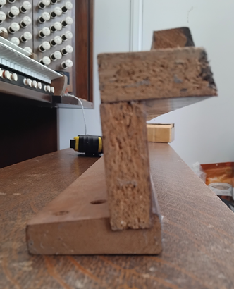
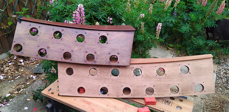
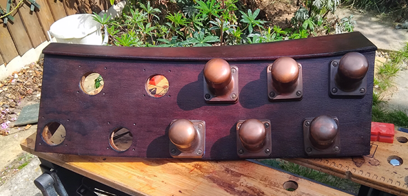
The rocker-tab bar is now with the joiner. He doesn’t think it will be a big job, but I also need to send him some veneer to apply. Naturally enough, I don’t have quite enough veneer remaining, so I’ve had to order another batch. Grr.
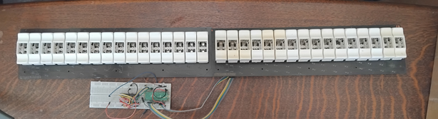
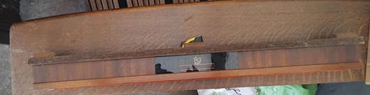
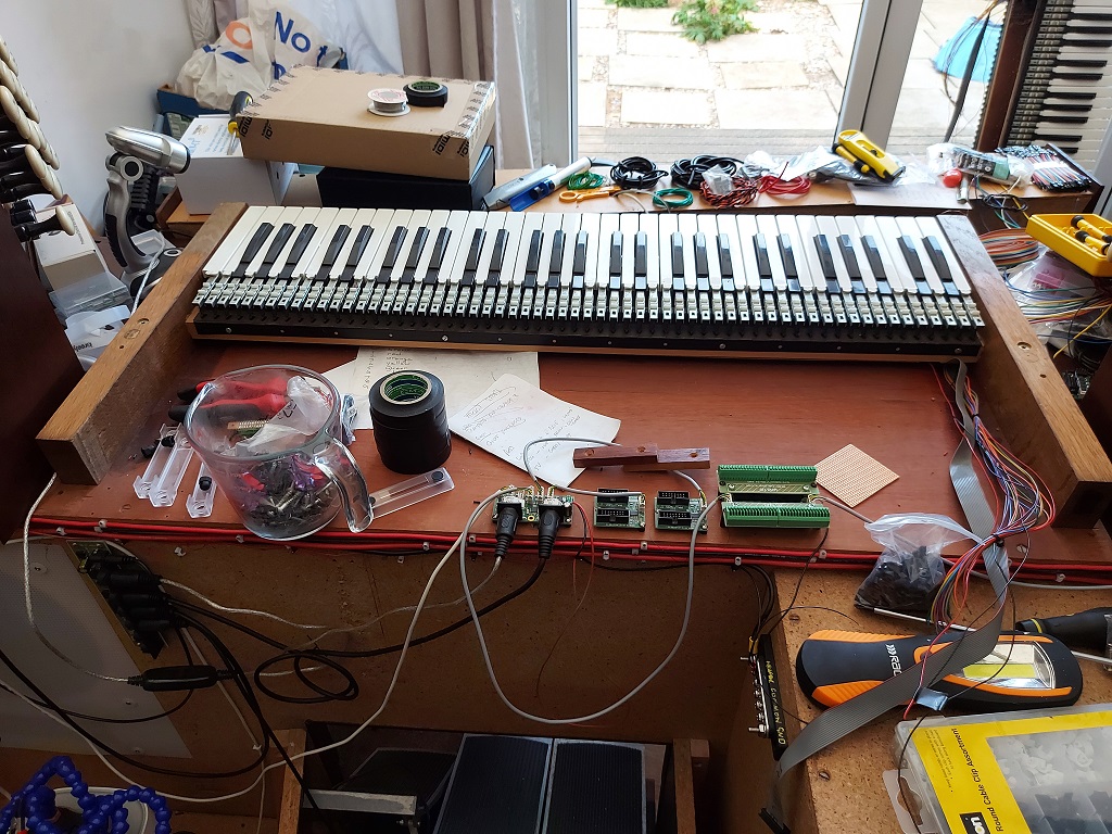
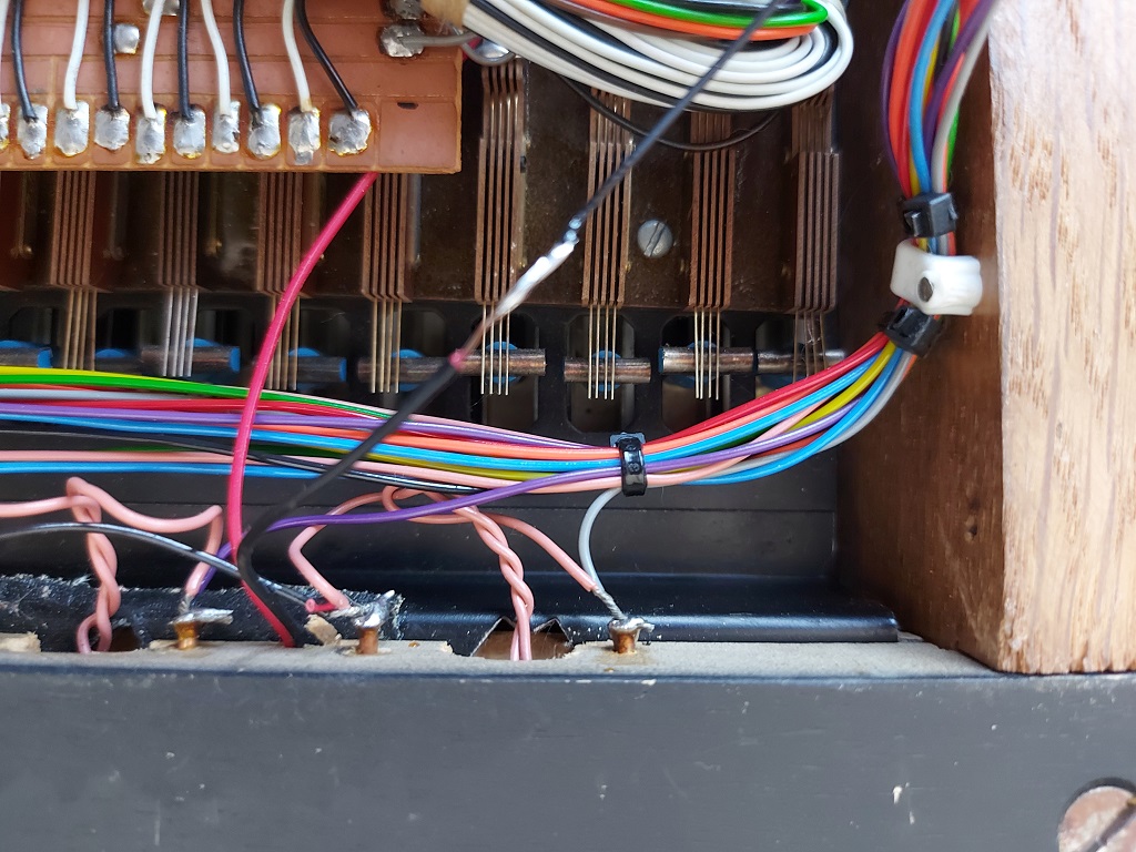
Meanwhile, here is what the back of the organ currently looks like. It’s mostly so that I have a reminder of what is going where, but others may find it instructive.
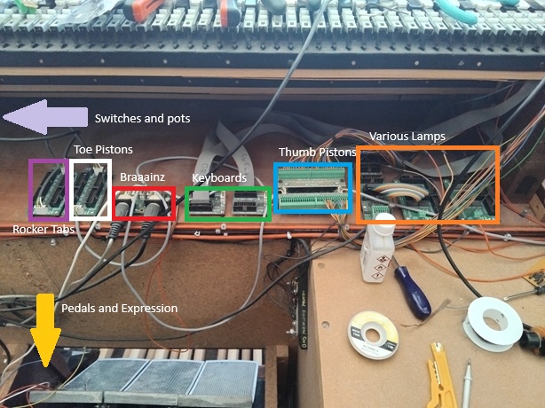
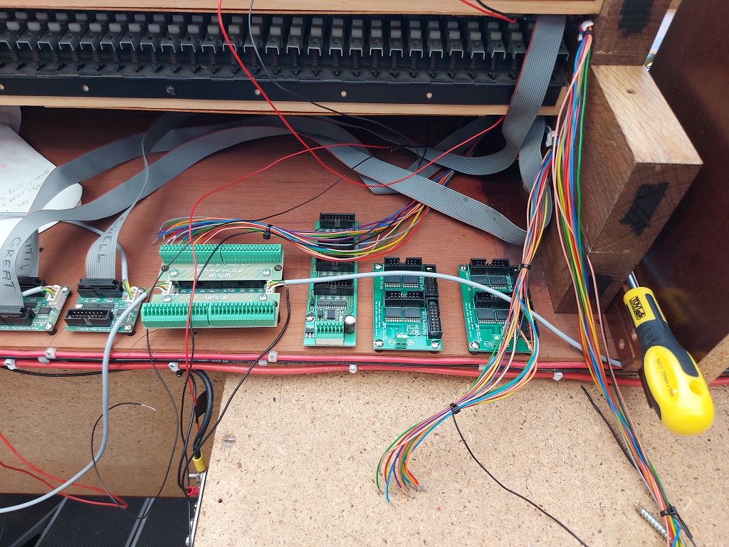
- Red: The brains. This is the board which actually sends (and sometimes receives) MIDI messages. All of the components which will send events to Hauptwerk go through here.
- Green: The keyboards. There are three physical keyboards, and they are plugged in here.
- Yellow (not shown): The pedalboard and expression shoes. This module is actually on the pedalboard itself, and connected by a long wire.
- Blue: Thumb pistons. All of the pistons under the keyboards go through this module.
- Orange: Lamps. This is a MIDI-IN module, and turns various lights on and off when it receives the appropriate MIDI signal: the rocker tabs and the Solo indicator.
- White: Toe pistons. Like the thumb pistons, but for the feet.
- Dark purple: Rocker tabs. These are on-off signals from the rocker tabs.
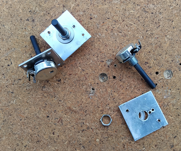
- Light purple (not shown): Various switches and pots on the console – they were already there, so they can be wired up if I can come up with a good reason for them.
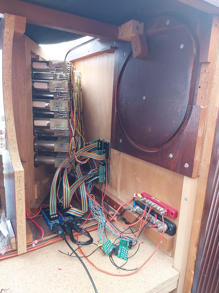
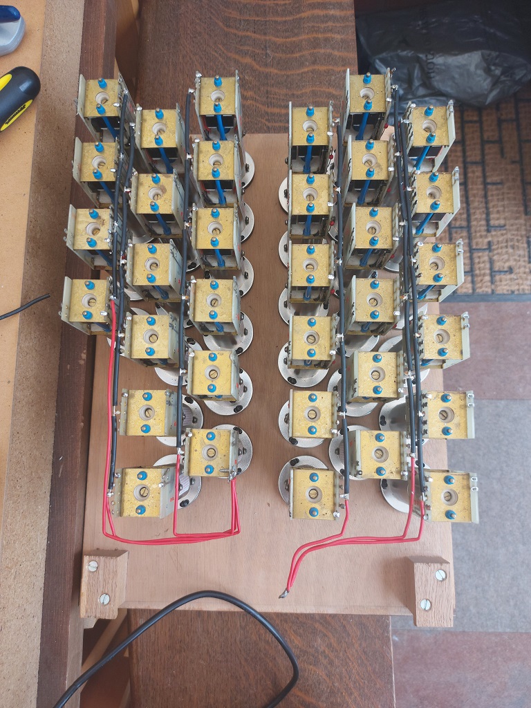
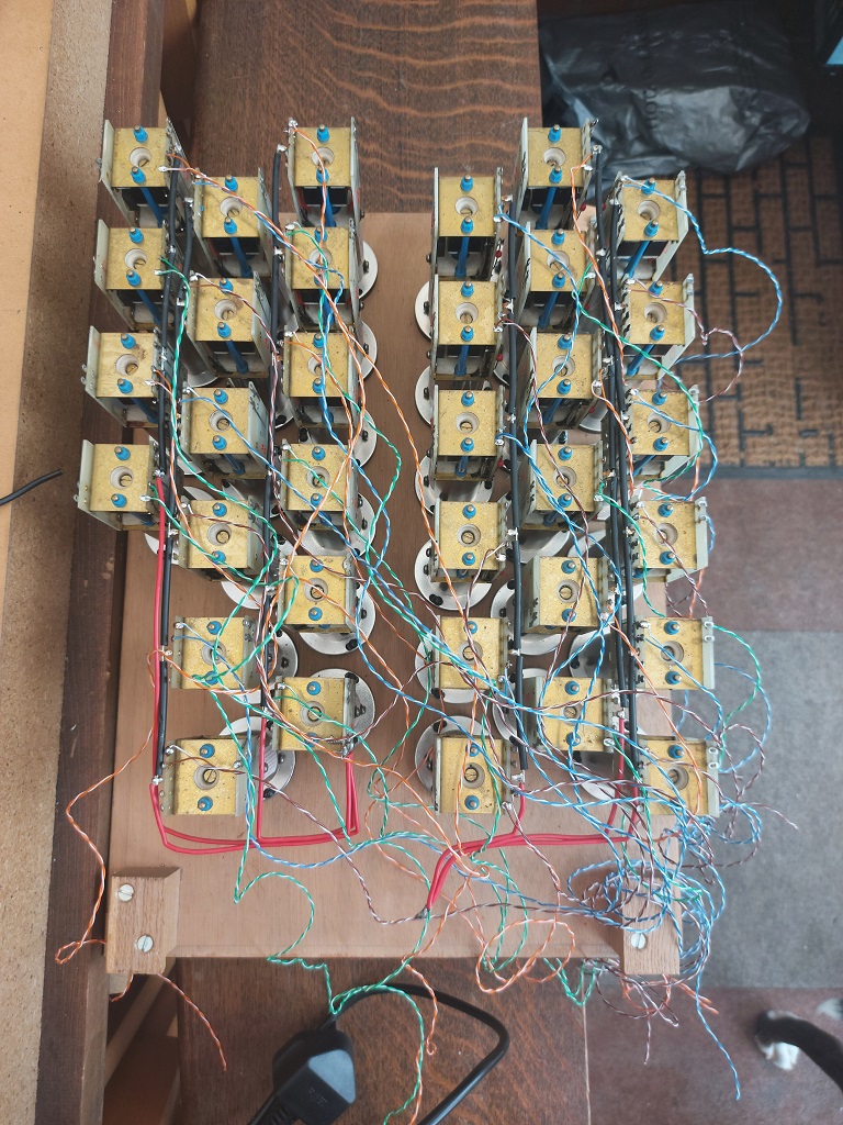
Also not shown in this photo are the drawstop subsystems, which are in/out components. A MIDI-OUT message is generated when pulling out (or pushing in, for that matter) an individual stop, but MIDI-IN messages are also received and activate the individual drawstop solenoids. This means that depressing a thumb- or toe-piston can change the registration mechanically.
The next job, while I’m waiting for the rocker-tab bar to be returned, is to wire up the toe pistons. Once that’s done, the organ will theoretically be playable through my laptop, at least in a small way.