I have made a start on the left-hand stop jamb. This one has 34 drawstops, and no added extras. Hopefully it won’t take too long to wire everything up, having learned from my previous mistakes, but there will then be a pause until the last order of components arrives from Midi Hardware. Given the ongoing component shortage, this could take until August. Oh well, there are several other things going on at the moment, and I’m not going to be bored.
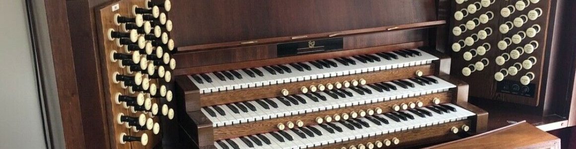
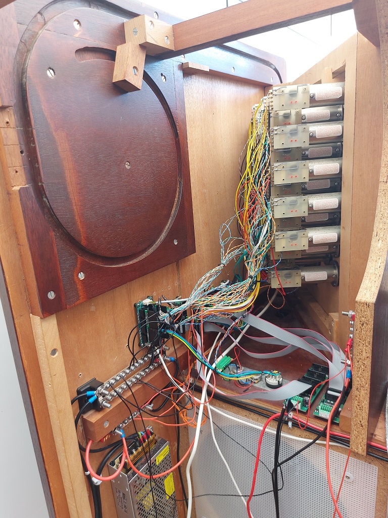
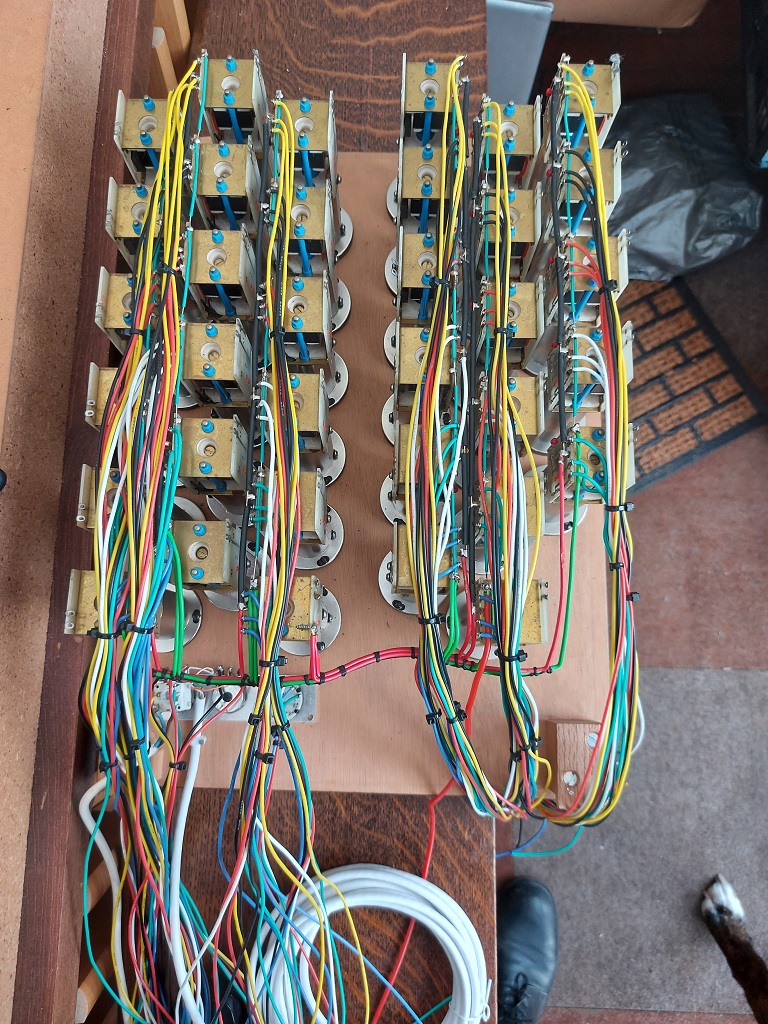
Finally, after five painful months of soldering, unsoldering, resoldering, replacement pots, replacement wires, replacement reed switches and more, the right-hand jamb is finished. All 35 drawstops send the correct signal when drawn on, and again when put off. Each of the stops can be activated or deactivated by MIDI messages, which are converted into solenoid pulses. There are two 3-way rotary switches, and four pots, all of which send the correct messages when fiddled with. There are no stray messages being sent anywhere. It all works.
The finished article
I need to shorten and/or tack up a few wires, but the work is essentially complete.
I have already prepped the left-hand jamb, to which I now need to solder 138 wires, but first I need to extend the 12V, 18V and GND lines across to the other side of the console.
Time to order more wire. By the end of the project, I will have used more wire than ITER.
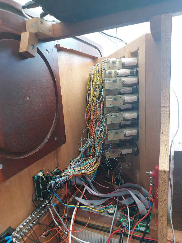
I am pleased to report that the SAMs all work exactly as they are intended to work. Everything is now wired up on the right-hand jamb, and all MIDI messages are generated and received correctly.
There is a little bit of noise from one of the pots, which only appears when both MIDECO boards are wired up. There is no connection between the MIDECO and the POT12 controllers, so RFI must be the culprit again. Moving the POT12 board removes most of the noise, and reducing the bit field of the pot removes the rest. This means that there is one pot with range of 0-31 (compared to 0-63), but that won’t be a problem. David is going to, ahem, ferrite out some ferrite beads to see if they help.
There are two sticky pistons. From the names on the stops (Great Enclosed, and Trompette En Chamade 8), I suspect that they were rarely used in the Lady Chapel of Buckfast Abbey – this may explain it. As per David’s instruction, I’m going to dismantle them both and see what is wrong.
So I get to dismantle the jamb again. Yea, verily, my cup runneth over.
I shudder to think how many times I have removed and re-inserted the stop jamb into the console, and my mind shies away from the enormity of the number of times I have re-soldered connections. But… it might now be complete (subject to final testing). The (new) pots and rotary switches are all working. The reed switches are all working. The SAMs were working, but who knows if they still are? I will test them this evening.
The once-neat power runs are a mess again, due to further modifications. I needed a 12VDC busbar for the various things which need that kind of power. I will need a similar busbar on the other side of the console, when I get to it. The GND needs extending over there as well. That is all a headache for another day. At some point, assuming the SAMs are functional, I will have to order Yet More Wire to start wiring up the left jamb. Hopefully, having made all my mistakes on its sibling, this will go easier. (I’m assuming nothing.)
Still need to reattach the toe pistons when David has finished putting them together, and I also need his help to fix a couple of stiff drawstops.
Upon request, I am furnishing a list of all the MIDI parts I am using at the moment. This list will expand as the organ nears completion, and it a good idea to take stock of the story so far.
The MIDI subsystem entwines its tendrils throughout the console. Its job is to translate analogue signals – such as playing the keyboards, pulling out drawstops, and exercising the expression shoes – into digital ones. These digital signals are processed by the computer when running suitable software (such as Grandorgue or Hauptwerk), which acts as the brain of the instrument. It also works in the opposite direction: digital signals can be translated into SAM pulses to turn drawstops on or off. The MIDI subsystem is essentially the nervous system of the instrument. Now, on with the list. (All components are from Midi Hardware unless otherwise stated.)
The List
MRG2: The cortex of the MIDI subsystem, which connects all the other input modules. The MRG2’s job is to encode signals using the MIDI protocol and transmit them to the computer.
DMS-2K: There are two of these. Each of them can connect to up to two keyboards in matrix configuration. The Great and Swell are attached to one, and the Choir/Positive to the second (with one spare).
PEDSCAN: This module connects the pedals (and expression shoes).
POT12: This little module connects all the pots (except for the ones on the expression shoes).
BBS-1K: There are three of these: one for thumb- and toe-pistons, and one for each stop jamb. Their job is to signal pistons being pressed, stops being drawn, and switches being turned.
MIDECO: Two of these for each stop jamb. They receive MIDI messages and convert them into signals for the SAMs.
MIBO-LITE: Three per stop jamb. They are the interface between the MIDECO modules and the SAMs. The SAMs need 18V, which is far more than can be provided by the MIDECO: it breaks a sweat at 5V.
There is also a MIDI splitter, which splits the MIDI-IN port across the MRG2 and MIDECO modules. This came from MIDI Boutique. It’s a nice board, but it probably won’t be needed in the long term.
I have now reached a temporary pause, while I wait for some more toys components to arrive over the course of April. Next on the agenda is to replace the remaining two pots and wire them into the POT12. Then, fix a couple of sticky drawstops (need David’s advice and help for that).
This post is long overdue, but I wanted to be at point where I could end on a positive note. Were Hercules to sin against Apollo today, he might be sentenced to solder, unsolder, and resolder some fiddly little terminals until, blinded by his tears, he burns his thumb.
I once had a plan. A beautiful plan, that made one weep to gaze upon. Well, hubris will always receive its payment. My plan is in ashes. It has been torn to pieces, buried in Soft Pete for three months, and recycled as firelighters. The amount of interference experienced by the switches was simply impossible to manage. The problem originally looked exactly like hysteresis, and I spent many fruitless hours trying to fix something that was not broken. In the end, after much advice from several very clever people, I was able to establish that “there’s no such thing as a common ground in an installation as big as an organ console”.
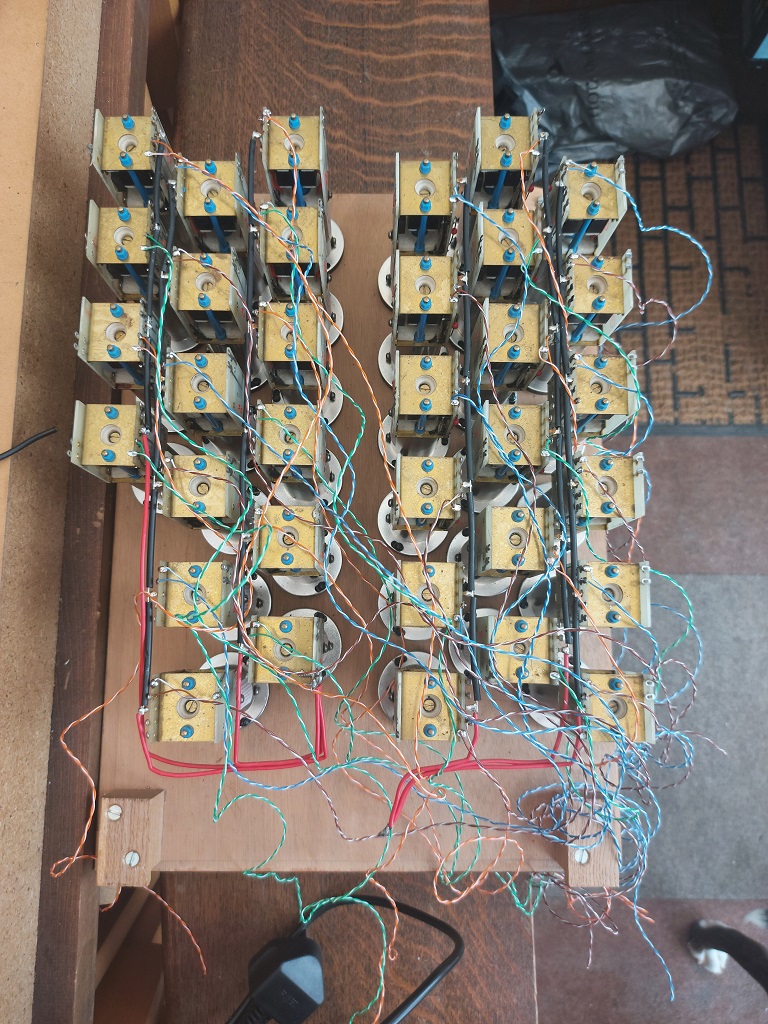
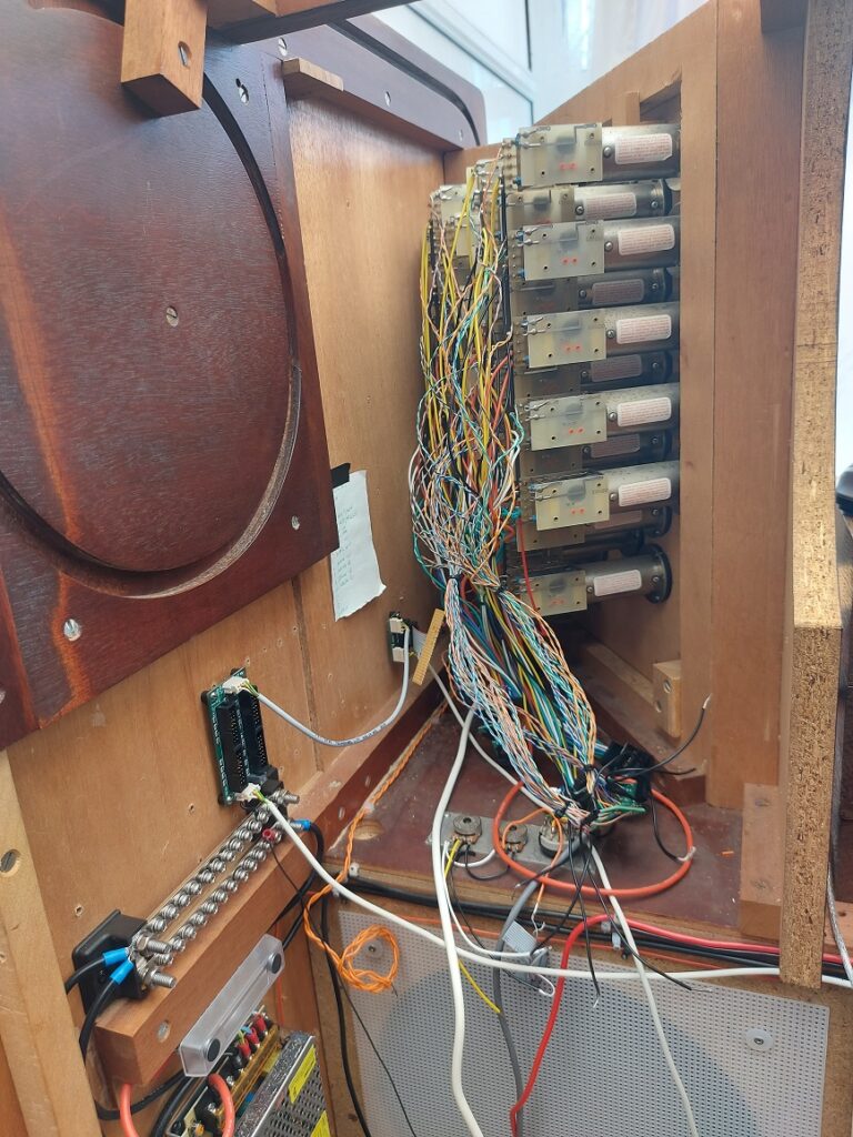
Cue a mass-desoldering of all the signalling wire from the stops, the removal of the hand-made connection boards I was so proud of, and a re-wire using twisted pair, with each ground going right back to the MIDI module and terminating right next to it. This has resulted in perfectly well-behaved drawstops on the right-hand stop jamb. This has taken me altogether too long to accomplish, and has been a remarkably stressful experience. I am a wiser man. Also, sadder.
I have also taken this opportunity to replace the old (and very noisy) pots on this jamb, and replace them with nice new ones. These are less noisy, and after proper configuration of the pot MIDI module, they are behaving exactly as they should.
On the plus side, David has examined my soldering and pronounced it “improved”. So there is that.
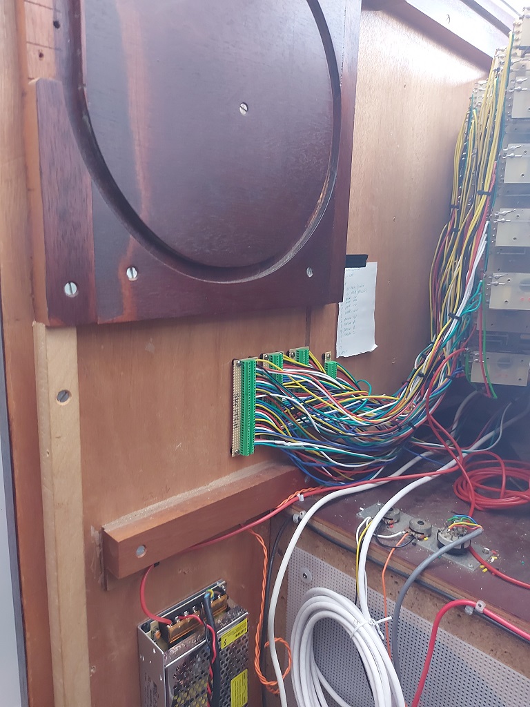
Twisted pairs to each drawstop, prior to connecting to the MIDI nerve centre.
After an immensely frustrating several days, during which I have taken the organ to pieces, unit-tested things which were known to be functional years ago, replaced reed switches, drunk lots of coffee, cried extensively, taken my shoes off and jumped on them, and basically been a drama queen, I have learned two important lessons.
Lesson 1: An oscilloscope would be a good investment.
Lesson 2 (which would have been learned more quickly if I had observed lesson 1): establish a good ground.
More to come, at some point, when I’m not so cross. Also, I need to tidy up a bit.
Also, why does my dog keep trying to eat lumps of wood and bits of wire? It’s not like he doesn’t have a whole box of toys and far too much food…
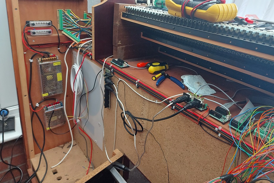
I have had a re-think about connecting the drawstops, and am awaiting the delivery of more toys from Midi Hardware. Until then, I will occupy myself with other matters, such as tidying up the power distribution.
Much better. After discussions with a clever person, I have combined the 0VDC from both PSUs to create a common GND. This simplifies the wiring somewhat.
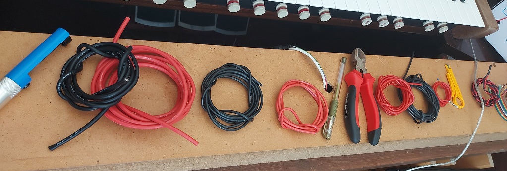
Here are some of the different lengths (and thicknesses) of wire I used. #nonewfuturama
I am now dreaming about wire. It is entirely possible that I will be able to wire the left-hand jamb in my sleep.
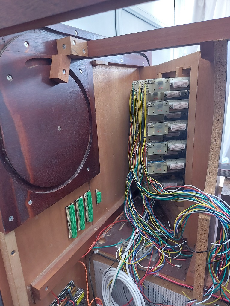
Over the last two weeks I have wired up the right-hand jamb, tested it, and screwed everything back into place. This has been a painful experience, requiring several hours of bending over in an awkward position. I confess to a distinct lack of enthusiasm about doing the whole thing again for the other jamb.
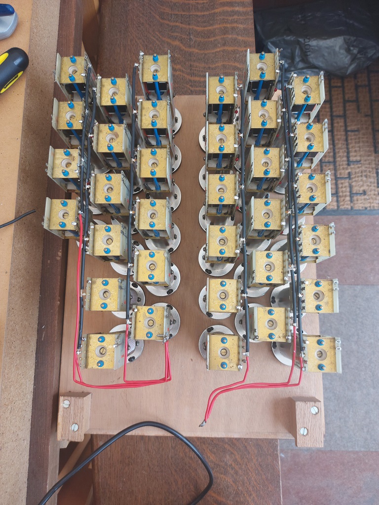
Each stop jamb has two feeds: a 12VDC input to the reed switches, and an 18VDC input to the electromagnets (two on each stop). Activating the lower magnet pushes the stop out, and activates the reed switch, while activating the upper magnet pulls the stop back in and deactivates the reed switch. Activating both magnets at the same time causes the culprit to be placed on the Interpol Most Wanted list. As an extra bonus, this jamb also includes the on/off relay switch (incorporating a pot), a second pot, and a 3-way rotary switch. I’ve wired these up too, although I’m not sure just yet what I will use them for.
The next stage of the process is to install the MIDI hardware which converts between electrical signals and MIDI messages. The reed switch signal pathway is fairly easy – it’s basically the same as for the pistons. On the other hand, the electromagnet switching is a whole new world of exploration. I’ll make a start on it next weekend.
This website stores cookies on your computer. These cookies are used to provide a more personalized experience and to track your whereabouts around our website in compliance with the European General Data Protection Regulation. If you decide to to opt-out of any future tracking, a cookie will be setup in your browser to remember this choice for one year.