I have been introduced to draw.io. I am hooked.
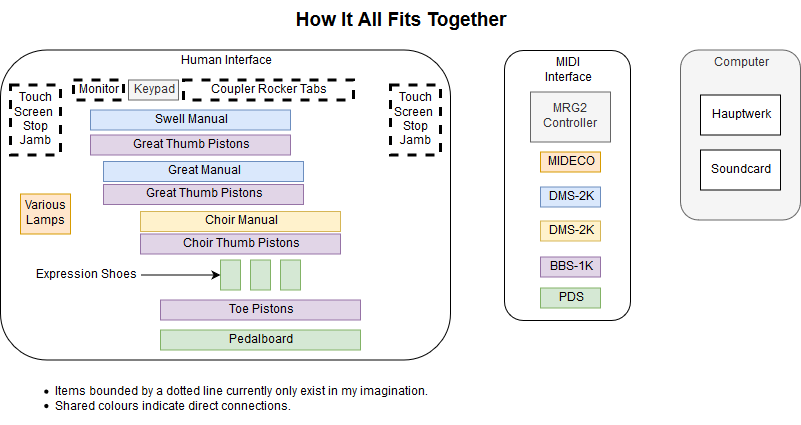
I have been introduced to draw.io. I am hooked.
My stand-offs have arrived, and also the wrong screws (wanted M3, but seem to have ordered M2 for no discernable reason). To pass the time, I ordered the pedalboard reed switches and MIDI interface. That’s another £115.
I have a bit more free time next week, so I do hope I will be able to spend some of it on the project. I want to get cracking with the piston interface, but I need to get the MIDI modules secured first.
Not much free time this weekend, but there’s not a lot I can do with the organ at the moment either. I am waiting for some nylon stand-offs to arrive (around Wednesday, I estimate) so that I can affix the various MIDI components to the console. Once that is done, I will begin the laborious process of connecting up the pistons. The MIDI channels I will be using are:
1: Great
2: Swell
3: Choir
4: Pedal
5: Pistons (thumb and toe)
6: Tabs
7: Control
…although this scheme is subject to alteration approximately as and when I feel like it. I also have to read the documentation to see if the toe pistions go through the pedal controller. I know the expression pedals do. I would prefer all the pistons to go through a single controller and on a single channel, but I’m not wedded to the idea.
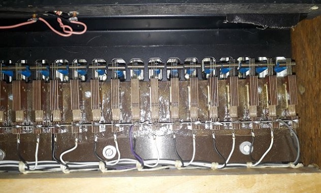
Meanwhile, this evening I indulged in a little creative destruction. The pedalboard contacts are a mixture of 3-wire and 4-wire contacts, and are badly damaged. Those which are not damaged are corroded:
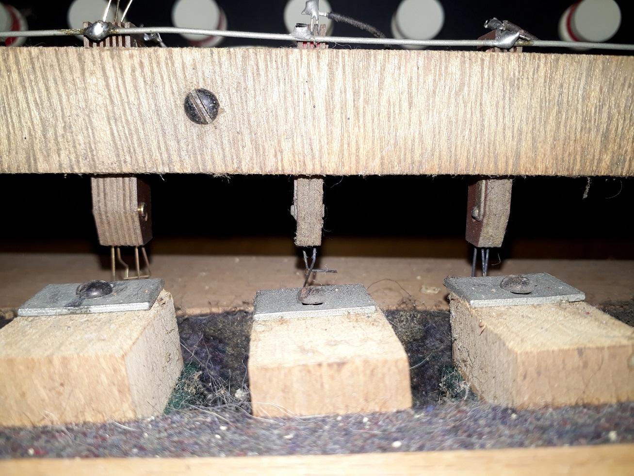
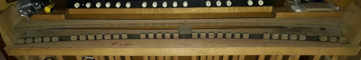
Given a choice of cleaning the corroded contacts and replacing the damaged ones, or swapping the whole lot out for reed switches, the choice of the latter was the obvious one. Reed switches, which are controlled by proximity magnets, are a bit fiddly to set up initially, but once installed are far more reliable and need no maintenance. So this evening I removed the old contact assemblies. Here is the denuded pedalboard, just needing a bit of a brush down. You can clearly see where the contacts were secured.
I have two new strips of pedal felt, but on closer inspection of the business end of the pedals it would appear that the existing felt is in fairly good condition, and not significantly compacted. Still debating whether or not to replace it.
For now, I believe it is time for tea.
Well, more-or-less. All bar tacking down the ribbon cable of the swell manual, anyway. And at some point I will probably build replacement diode matrices. But for now, it is done.
I needed to convert the bus-bar from banks of 5 8 8 8 8 8 8 8 to 8 8 8 8 8 8 8 5, as seen here:
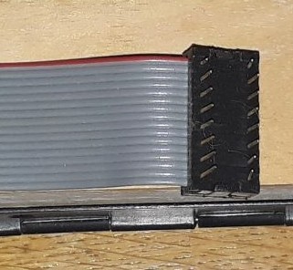
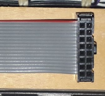
And also to replace the old plug:
And then re-wire the ribbon cable in a very peculiar way (not pictured, because it hurts to look at).
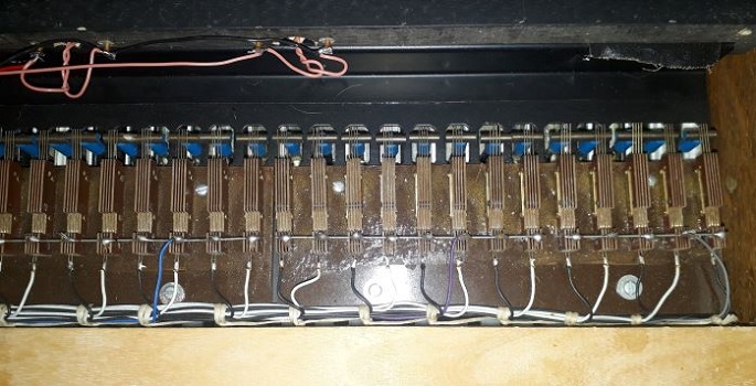
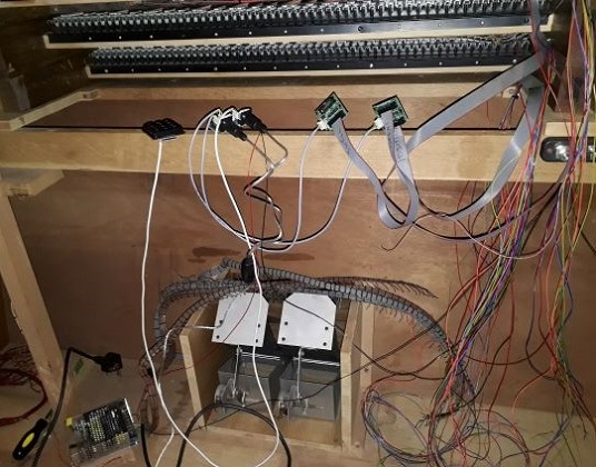
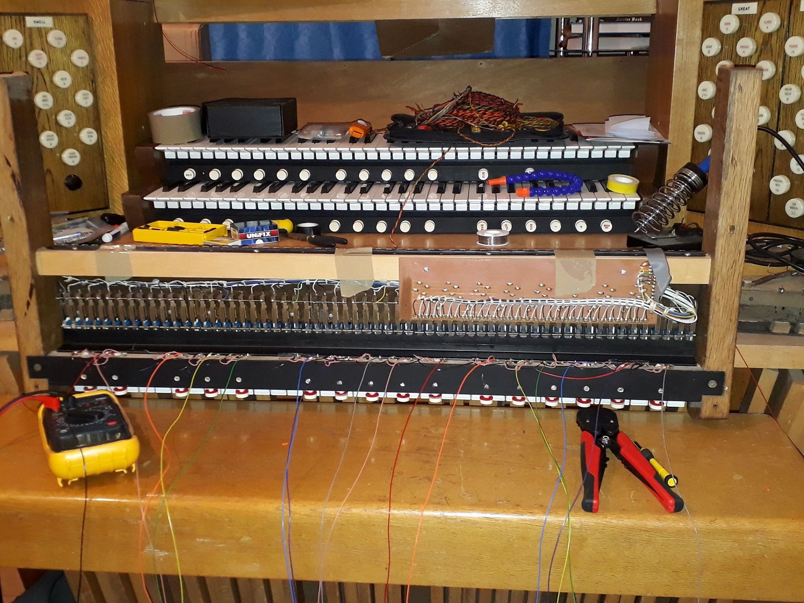
Nevertheless, I now have three manuals that all send the correct MIDI messages on the correct channels. Next major job is to wire up the pistons, but first I need to make sense of the entropy at the back of the organ:
This evening, having found myself in possession of a MIDI numeric keypad (which makes it so much easier to issue commands to the MIDI hardware), I put my theories to test on an as-yet-unmodified keyboard. I replicated the ribbon-cable arrangement from the choir manual, but left the busbar unmodified. Cycling through the four configurations possible on the keyboard scanner card, I was able to confirm that configuration 3 is the correct one, that the ribbon-cable arrangement is correct, and that I do in fact need to adjust the bus-bar.
So the plan for tomorrow is to secure the ribbon cable on the choir manual, and complete the modifications to the great. I will try and do the swell on Friday, but the weekend is looking to be very busy. Next week I will think about where to affix the MIDI modules, and also start work on the piston wiring.
After much tea and tantrums, soldering, unsoldering, resoldering, snipping wires, and the much more complicated task of unsnipping wires, I now have the choir manual sending coherent MIDI messages to the computer. It sends NoteOn and NoteOff for notes 39-99. My joy is only slightly marred by the fact that it should be sending messages for notes 36-96. Fortunately, that can be corrected by configuring the MIDI controller. I’m just waiting for another bit of MIDI hardware to arrive and I should be able to get on and do exactly that.
Once I’ve established the precise method of configuring the choir manual, I can replicate it (hopefully with a lot less soldering) on the great and swell manuals. Then I can start doing things with those pistons which have occupied so much of my spare time over the last few months.
Ok, so I’ve wired up the choir manual to the MIDI scanner, plugged the scanner into the MIDI controller, given that some volts, plugged it into the MIDI-to-USB converter, and I am now watching MIDI messages appear on my laptop screen. They’re all in the wrong order, which is vexing and requires further consideration. At the moment it’s a bit like this (from imgur, alas I don’t know the creator):

But the important thing is that I NOW HAVE MIDI MESSAGES GOING FROM THE KEYBOARD TO THE COMPUTER!
This pleases me greatly, and I am going to have a cup of tea. With a celebratory biscuit.
Is 47 kΩ. This illuminates without burning my retinas.
Having identified the correct value, I’ll do the soldering tomorrow. Not in the mood tonight.
Only one post for this manual, because I can only think of one pun (and even that is obscure).
Here we see the choir manual with all the pistons soldered and tested. Tomorrow’s job, if I have time, is to find the correct resistor for the LED solo division indicator, and solder it in. These LEDs are particularly bright, even with a relatively hefty resistor (if resistors can be said to have heft). The trick will be to find the right value to give a soft illumination, rather than being bright enough to read by.
The next step will be to re-solder the ribbon cables to meet the requirements of the MIDI interface board, and change the plugs. Then it will be time to think about where to affix the MIDI components.
I am unreasonably pleased about discovering that I have another reel of the Right Sort of Solder.
I may need an intervention.
(Choir manual nearly done.)