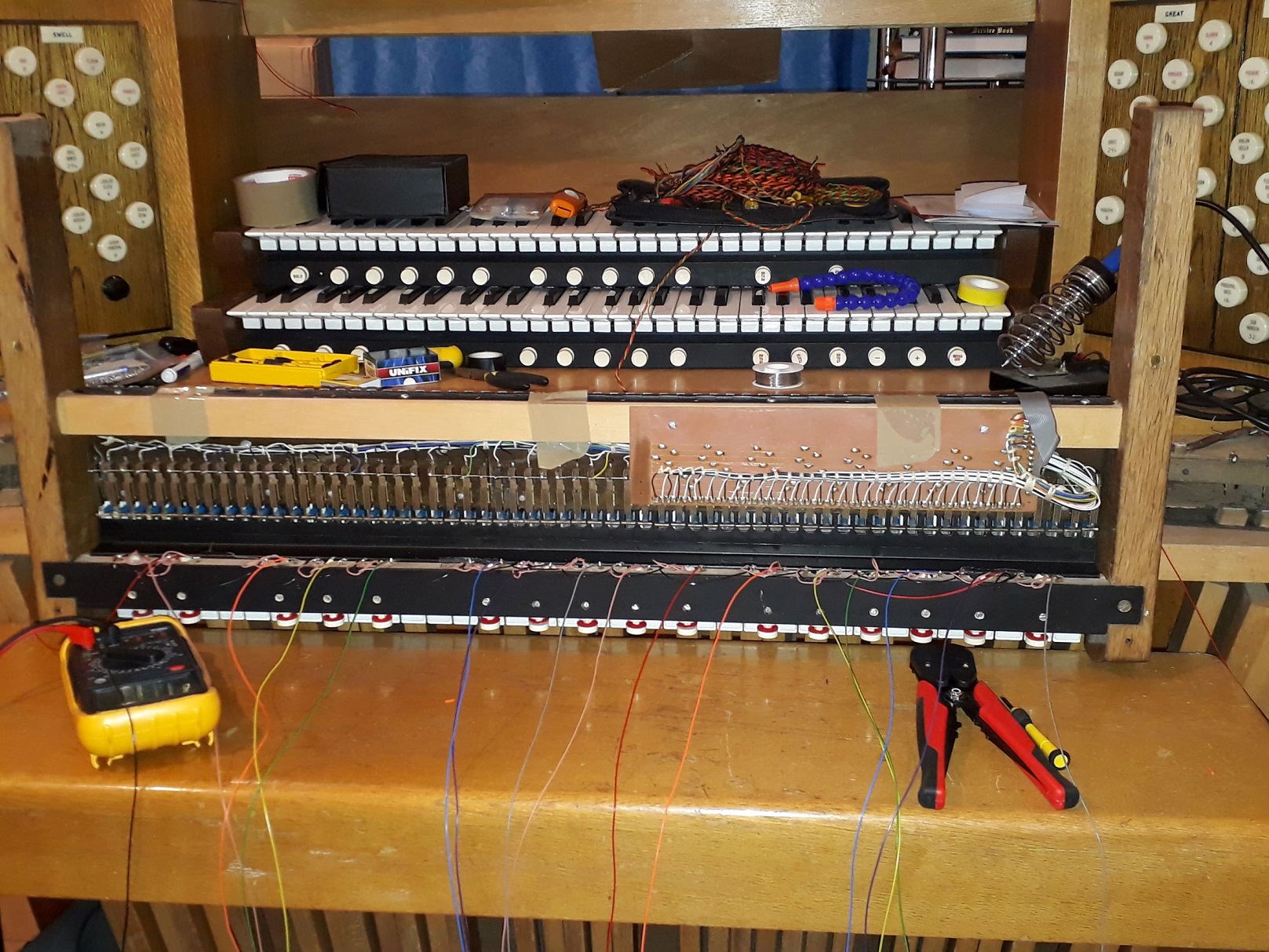
St Fulbert

Only one post for this manual, because I can only think of one pun (and even that is obscure).

Here we see the choir manual with all the pistons soldered and tested.  Tomorrow’s job, if I have time, is to find the correct resistor for the LED solo division indicator, and solder it in.  These LEDs are particularly bright, even with a relatively hefty resistor (if resistors can be said to have heft).  The trick will be to find the right value to give a soft illumination, rather than being bright enough to read by.

This photo has been eaten by a grue

The next step will be to re-solder the ribbon cables to meet the requirements of the MIDI interface board, and change the plugs.  Then it will be time to think about where to affix the MIDI components.

Great (Balls of Fire)

Here is the completed great manual.  Soldering has much improved this time around.  You may notice a resistor soldered to the LED.  Ignore it, it is useless.  I need a bigger one.

This photo has been eaten by a grue

One more to go, then I can start thinking about wiring them up to the MIDI modules.

Bit hard to work on this at the moment, as Mia has just died from cancer.  Went from limping a bit, to a terminal diagnosis, to dead, within 3 weeks.  A bit overwhelming, really.

And now for something completely different.

Taking a break from the unending boredom that is soldering small bits of wire to other small bits of wire (people still do this for hours every day?!), I have now attached the first new component to the console.  To wit and viz.  : –

This photo has been eaten by a grue

It might not look much to you, but it’s a busbar to me.  This is where the reference GND/-ve/0V/wossname wires will be safely gathered in, and sent back to the -ve terminal on the 12V PSU.  First the keyboards, then the pedalboard, then the tabs, then… ah, but I get ahead of myself.


Swell

The helping hands turned out to be no help whatsoever.  Never mind.  The swell manual is finished (apart from the ribbon cable, of which more later), the contacts tested, and the pistons secured.  The soldering is bloody awful isn’t the best, but it does the job: all the pistons pull to GND when depressed.  I’ve learned several lessons during my painful attempts at soldering this manual, which I will apply to future efforts.  The two most important being: Solder isn’t expensive, so don’t scrimp; and, flux is your friend.  But first, more coffee.

Pictures are during and after.  Don’t look to closely at the soldering; I gave serious consideration to blurring it out, until I remembered that I was taking the pictures with a potato anyway.

This photo has been eaten by a grueThis photo has been eaten by a grue

Slow going…

So, chatting to the friendly organ engineer about the problems I was having with getting the solder to adhere to the nasty nickel-plated steel screws, I got a wise “yes, they’ll do that” sort of response.  The replacement brass screws were duly purchased, 96 steel screws were unscrewed, and 96 brass alternatives were installed.  Some of the holes are a little loose, which is irritating, but should easily be secure enough to remain where they are supposed to remain.  A spot of epoxy might be in order.

Now I’m beginning the labourious process of soldering two or three wires to each post.  This is challenging to say the least.  I’m waiting for the arrival of some helping hands, which I hope will make it less awkward.

All my jobs are running somwehat slowly at present, due to the news I received last week that poor Mia has inoperable cancer.  She’s soldiering on, aided by copious quantities of painkillers, and is dividing her time between sleeping, eating and watching squirrels.  She seems quite happy at the moment, but her days are numbered, quite severely.  A few weeks at best.

I should know better than to make predictions.

So much for a January noise-production.

Cheap, nickel-plated screws, even heavily abraded with the dremel, do not good solder posts make.  Nothing I have done has been able to convince the solder to stay attached to the screw.  Vexing.

So I have just received a pack of rather more expensive brass screws of the same pitch and length, and this weekend I shall replace all ninety-six of the old new screws (which shall be flung into the outer darkness or, at least, the recycling bin) with new new ones.  And then try soldering again.  If this doesn’t work, I shall scream and swear, and generally throw a tantrum.

Pist off

I can’t get the solder to stick to the terminal screws, which is something of a vexation.  I’m fairly sure the iron is heating the screws sufficiently, since they make the wood smoke.  I have ordered some liquid flux, which I hope will help.  In the meantime, all 43 pistons have now been inserted into the correct holes and screwed down.  Beautiful, isn’t it?

This photo has been eaten by a grue

A Tale of 43 Pistons (a continuing series)

Here they all are, tailed-up and continuity-tested…

This photo has been eaten by a grue


Now begins the task of inserting and securing them into the holes to which they have been allocated…

This photo has been eaten by a grue

And here is the front face of the swell manual.  A small screw is used to hold each piston in place.  Note the ‘SOLO’ button in green on the left, next to an LED.  This will be configured so that a solo division can be swapped onto the manual, whenever the button is pressed.  If I am clever enough, I will make it so that selecting the solo division on any manual will restore any other manual with solo selected to its original division.  Pressing the piston a second time will also do this.  That’s the theory, anyway.

This photo has been eaten by a grue

The regretful fly in my ointment of productivity is that I purchased the wrong size of small screws – M2 instead of M4.  Oh well, off to the screw shop again.

Next Page » « Previous Page